Frames
The org.orekit.frames package provides classes to handle frames and
transforms between them.
Frames Presentation
Frames tree
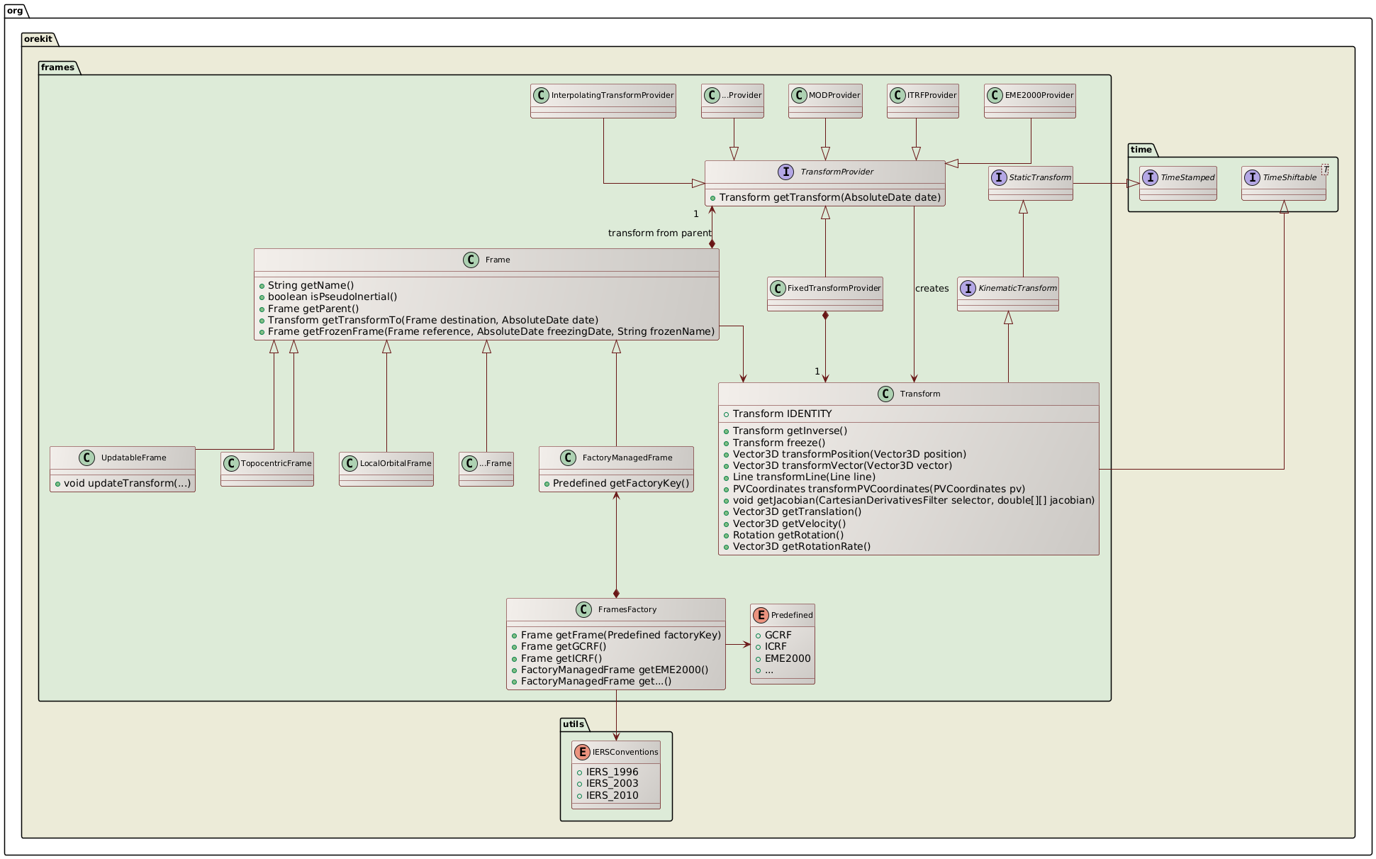
The Frame class represents a single frame. All frames are organized as a
tree with a single root.
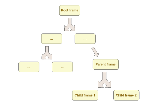
Each Frame is defined by a single TransformProvider linking it to one specific frame:
its parent frame. This defining transform provider may provide either fixed or
time-dependent transforms. As an example the Earth related frame ITRF depends on time
due to precession/nutation, Earth rotation and pole motion. The predefined root frame
is the only one with no parent frames.
For each pair of frames, there is one single shortest path from one frame to the other one.
Transform
The Transform class represents a full transform between two frames. It manages
combined rotation, translation and their first time derivatives to handle kinematics.
Transforms can convert position, directions and velocities from one frame to another
one, including velocity composition effects.
Transforms are used to both:
-
define the relationship from a parent to a child frames. This transform (
tdefon the following scheme) is stored in the child frame. -
merge all individual transforms encountered while walking the tree from one frame to any other one, however far away they are from each other (
trelon the following scheme).
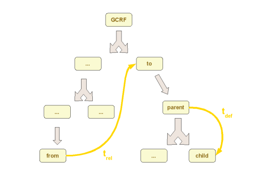
The transform between any two frames is computed by merging individual transforms while walking the shortest past between them. The walking/merging operations are handled transparently by the library. Users only need to select the frames, provide the date and ask for the transform, without knowing how the frames are related to each other.
Transformations are defined as operators which, when applied to the coordinates of a
vector expressed in the old frame, provide the coordinates of the same vector expressed
in the new frame. When we say a transform t is from frame A to frame B, we mean
that if the coordinates of some absolute vector (say, the direction of a distant star)
are uA in frame A and uB in frame B, then uB=t.transformVector(uA).
Transforms provide specific methods for vectorial conversions, affine conversions, either
with or without first derivatives (i.e. angular and linear velocities composition).
Transformations can be interpolated using Hermite interpolation, i.e. taking derivatives into account if desired.
Predefined Frames
The FramesFactory class provides several predefined reference frames.
The user can retrieve them using various static methods: getGCRF(), getEME2000(),
getICRF(), getCIRF(IERSConventions, boolean), getTIRF(IERSConventions, boolean),
getITRF(IERSConventions, boolean), getMOD(IERSConventions), getTOD(IERSConventions),
getGTOD(IERSConventions), getITRFEquinox(IERSConventions, boolean), getTEME(),
getPZ9011(IERSConventions, boolean), and getVeis1950().
One of these reference frames has been arbitrarily chosen as the root of the frames tree:
the Geocentric Celestial Reference Frame (GCRF) which is an inertial reference defined by IERS.
For most purposes, the recommended frames are ITRF for terrestrial frame and GCRF for celestial frame. EME2000, TOD, Veis1950 could also be used for compatibility with legacy systems. TEME should be used only for TLE.
There are also a number of planetary frames associated with the predefined celestial bodies.
IERS 2010 Conventions
One predefined set corresponds to the frames from the IERS conventions (2010). This set defines the GCRF reference frame on the celestial (i.e. inertial) side, the ITRF (International Terrestrial Reference Frame) on the terrestrial side and several intermediate frames between them. Several versions of ITRF have been defined. Orekit supports several of them thanks to Helmert transformations.
New paradigm: CIO-based transformations (Non-Rotating Origin)
There are several different ways to compute transforms between GCRF and ITRF. Orekit supports
the new paradigm promoted by IERS and defined by IERS conventions 2010, i.e., it uses a
single transform for bias, precession and nutation, computed by precession and nutation models
depending on the IERS conventions choice and the Earth Orientation Parameters (EOP) data published online
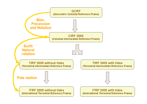
by IERS. This single transform links the GCRF to a Celestial Intermediate Reference Frame (CIRF).
The X axis of this frame is the Celestial Intermediate Origin (CIO) and its Z axis is the
Celestial Intermediate Pole (CIP). The CIO is not linked to equinox any more. From CIRF,
the Earth Rotation Angle (including tidal effects) is applied to define a Terrestrial
Intermediate Reference Frame (TIRF) which is a pseudo Earth fixed frame. A last transform adds
the pole motion (both observed and published in IERS frames and modeled effects including tidal
effects) with respect to the Earth crust to reach the real Earth fixed frame: the International
Terrestrial Reference Frame. There are several realizations of the ITRS, each one being a
different ITRF. These realizations are linked together using Helmert transformations which are
very small, slightly time-dependent transformations.
The precession-nutation models for Non-Rotating Origin paradigm available in Orekit are those defined in either IERS 1996 conventions, IERS 2003 conventions or IERS 2010 conventions.
In summary, five frames are involved along this path, with various precession-nutation models: GCRF, CIRF, TIRF, ITRF and PZ-90.11.
Classical paradigm: equinox-based transformations
The classical paradigm used prior to IERS conventions 2003 is equinox-based and uses more intermediate frames. It is still used in many ground systems and can still be used with new precession-nutation models.
Starting from GCRF, the first transform is a bias to convert to EME2000, which was the former reference. The EME2000 frame (which is also known as J2000) is defined using the mean equinox at epoch J2000.0, i.e. 2000-01-01T12:00:00 in Terrestrial Time (not UTC!). From this frame, applying precession evolution between J2000.0 and current date defines a Mean Of Date frame for current date and applying nutation defines a True Of Date frame, similar in spirit to the CIRF in the new paradigm. From this, the Greenwich Apparent Sidereal Time is applied to reach a Greenwich True Of Date frame, similar to the TIRF in the new paradigm. A final transform involving pole motion leads to the ITRF.
In summary, six frames are involved along this path: GCRF, EME2000, MOD, TOD, GTOD and equinox-based ITRF.
In addition to these frames, the ecliptic frame which is defined from the MOD by rotating back to ecliptic plane is also available in Orekit.
The so-called Veis 1950 belongs also to this path, it is defined from the GTOD by the application of a modified sidereal time.
This whole paradigm is deprecated by IERS. It involves additional complexity, first because of the larger number of frames and second because these frames are computed by mixed models with IAU-76 precession, correction terms to match IAU-2000, and a need to convert Earth Orientation data from the published form to a form suitable for this model.
Despite this deprecation, these frames are very important ones and lots of legacy systems rely on them. They are therefore supported in Orekit for interoperability purposes (but not recommended for new systems).
As the classical paradigm uses the same definition for celestial pole (Z axis) but not the same definition for frame origin (X axis) as the Non-Rotating Origin paradigm, the TOD frame and the CIRF frame share the same Z axis but differ from each other by a non-null rotation around Z (the equation of the origin, which should not be confused with the equation of the equinox), and the TIRF and GTOD should be the same frame, at model accuracy level (and of course ITRF should also be the same in both paradigms).
Orekit implementation of IERS conventions
In summary, Orekit implements the following frames:
-
those related to the Non-Rotating Origin: GCRF, CIRF, TIRF, ITRF for all precession and nutation models from IERS 1996, IERS 2003 and IERS 2010,
-
those related to the equinox-based origin: MOD, TOD, GTOD, equinox-based ITRF for all precession and nutation models from IERS 1996, IERS 2003 and IERS 2010 and Veis 1950.
The frames can be computed with or without Earth Orientation Parameters corrections, and when these corrections are applied, they can either use a simple interpolation or an accurate interpolation taking sub-daily tidal effects. It is possible to mix all frames. It is for example one can easily estimate the difference between an ITRF computed from equinox based paradigm and IERS 1996 precession-nutation, without EOP and an ITRF computed from Non-Rotating Origin and IERS 2010 precession-nutation, with EOP and tidal correction to the EOP interpolation. This is particularly interesting when exchanging data between ground systems that use different conventions.
CIO-based transformations
Here is a schematic representation of the partial tree containing the supported IERS frames based on CIO.
Since Orekit uses the new paradigm for IERS frames, the IAU-2006 precession and IAU-2000A nutation model implemented are the complete model with thousands of luni-solar and planetary terms (1600 terms for the x components, 1275 components for the y component and 66 components for the s correction). Recomputing all these terms each time the CIRF frame is used would be really slow. Orekit therefore implements a caching/interpolation feature to improve efficiency. The shortest period for all the terms is about 5.5 days (it is related to one fifth of the moon revolution period). The pole motion is therefore quite smooth at the day or week scale. This implies that this motion can be computed accurately using a few reference points per day or week and interpolated between these points. The trade-off selected for Orekit implementation is to use eight points separated by four hours each. The resulting maximal interpolation error on the frame is about 4e-15 radians. The reference points are cached so the computation cost is roughly to perform two complete evaluations of the luni-solar and planetary terms per simulation day, and one interpolation per simulation step, regardless of the step size. This represents huge savings for steps shorter than one half day, which is the rule in most application (step sizes are mostly of the range of a few tens of seconds). Note that starting with Orekit 6.0, this caching feature is thread-safe.
Tidal effects are also taken into account on Earth Rotation angle and on pole motion. The 71-terms model from IERS is used. Since this model is also computing intensive, a caching/interpolation algorithm is also used to avoid a massive effect on performance. The trade-off selected for Orekit implementation is to use 8 points separated by 3/32 day (135 minutes) each. The resulting maximal interpolation error is about 3 micro-arcseconds. The penalty to use tidal effects is therefore limited to slightly more than 20%, to be compared with the 550% penalty without this mechanism.
Equinox-based transformations
Here is a schematic representation of the partial tree containing the supported IERS frames based on equinox
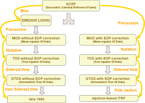
The path from EME2000 to Veis1950, involving the MOD, TOD and GTOD without EOP correction, is devoted to some legacy systems, whereas the MOD, TOD and GTOD with EOP correction are for compatibility with the IERS 2003 convention. The gap between the two branches can reach a few meters, a rather crude accuracy for many space systems.
The same kind of optimization used for the IAU-2006 precession and IAU-2000A nutation model are also applied for the older IAU-1980 precession-nutation model, despite it is much simpler.
Solar system frames
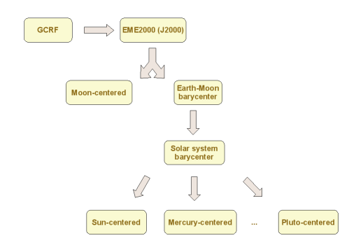
All celestial bodies are linked to their own body-centered inertial frame, just as the Earth is linked to EME2000 and GCRF. Since Orekit provides implementations of the main solar system celestial bodies, it also provides body-centered frames for these bodies, one inertially oriented and one body oriented. The orientations of these frames are compliant with IAU poles and prime meridians definitions. The predefined frames are the Sun, the Moon, the eight planets and the Pluto dwarf planet. In addition to these real bodies, two points are supported for convenience as if they were real bodies: the solar system barycenter and the Earth-Moon barycenter ; in these cases, the associated frames are aligned with EME2000. One important case is the solar system barycenter, as its associated frame is the ICRF.
Earth Frames
As explained above, the IERS conventions define Earth frames, the ITRF frames. Depending on which Earth Orientation Parameters are loaded at run time by users, the ITRF frame computed may be an older or a newer one. If EOP parameters are loaded from EOP C04 14 files, the ITRF will be ITRF 2014, whereas if EOP parameters are loaded from EOP C04 08, or from Bulletin A or from Bulletin B, the ITRF be be ITRF 2008. When IERS will update its references, the ITRF products change accordingly. Orekit knows about these changes and always allows to convert from one ITRF to any other ITRF or to get a specific ITRF version even if the loaded EOP were related to one or several different ITRF versions. As an example, one can load yearly EOP C04 files with some files referring to ITRF 2008, some other files referring to ITRF 2014, and use this mixed history to compute ITRF 2020: Orekit will manage the required Helmert conversions for each date internally, users do not need to bother about this. All ITRF versions since 1988 are supported. As of Orekit 12.0, it corresponds to ITRF88, ITRF89, ITRF90, ITRF91, ITRF92, ITRF93, ITRF94, ITRF96, ITRF97, ITRF2000, ITRF2005, ITRF2008, ITRF2014 and ITRF2020.
Topocentric Frame
This frame model allows defining the frame associated with any position at the surface of a body shape, which itself is referenced to a frame, typically ITRF for Earth. The frame is defined with the following canonical axes:
-
zenith direction (Z) is defined as the normal to local horizontal plane;
-
north direction (Y) is defined in the horizontal plane (normal to zenith direction) and following the local meridian;
-
east direction (X) is defined in the horizontal plane in order to complete direct triangle (east, north, zenith).
In such a frame, the user can retrieve azimuth angle, elevation angle, range and range rate of any point given in any frame, at given date.
Local Orbital Frame
Local orbital frames are bound to an orbiting spacecraft. They move with the spacecraft so they are time-dependent. Two local orbital frames are provided: the (t, n, w) frame and the (q, s, w) frame.
The (t, n, w) frame has its X axis along velocity (tangential), its Z axis along orbital momentum and its Y axis completes the right-handed trihedra (it is roughly pointing towards the central body). The (q, s, w) frame has its X axis along position (radial), its Z axis along orbital momentum and its Y axis completes the right-handed trihedra (it is roughly along velocity).
User-defined frames
The frames tree can be extended by users who can add as many frames as they
want for specific needs. This is done by adding frames one at a time, attaching
each frame to an already built one by specifying the TransformProvider from parent to child.
Transforms may be constant or varying. For simple fixed transforms, using directly the
FixedTransformProvider class is sufficient. For varying transforms (time-dependent or
telemetry-based for example), it may be useful to define specific providers that will implement
getTransform(AbsoluteDate).
A basic example of such an extension is to add a satellite frame representing the satellite
motion and attitude. Such a frame would have an inertial frame as its parent frame (GCRF or
EME2000) and the getTransform(AbsoluteDate) method would compute a transform using the
translation and rotation from orbit and attitude data.
Frames transforms are computed by combining all transforms between parent frame and child frame
along the path from the origin frame to the destination. This implies that when one
TransformProvider locally changes a transform, it basically moves not only the child frame but
all the sub-trees starting at this frame with respect to the rest of the tree. This property can
be used to update easily complex trees without bothering about combining transforms oneself. The
following example explains a practical case.
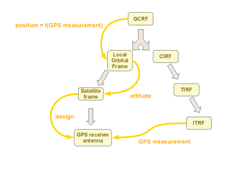
This case is an improvement of the basic previous extension to manage orbit and attitude. In this
case, we introduce several intermediate frames with elementary transforms and need to update the
whole tree. We also want to take into account the offset between the GPS receiver antenna and the
satellite center of mass. When a new GPS measurement is available, we want to update the complete
left subtree. This is done by using the dedicated UpdatableFrame which will do all the conversions.
Package organization
