We want to compute the Doppler effect of a satellite with respect to a ground station.
On the one hand, we define the Local Orbital Frame (LOF) related to the satellite.
Let's first define some initial state for the satellite with:
The initial orbit is just set as a CartesianOrbit. More details on the orbit representation can be found in the orbits section of the library architecture documentation.
Frame inertialFrame = FramesFactory.getEME2000();
TimeScale utc = TimeScalesFactory.getUTC();
AbsoluteDate initialDate =
    new AbsoluteDate(2004, 01, 01, 23, 30, 00.000, utc);
double mu =  3.986004415e+14;
Vector3D position = new Vector3D(-6142438.668, 3492467.560, -25767.25680);
Vector3D velocity = new Vector3D(505.8479685, 942.7809215, 7435.922231);
PVCoordinates pvCoordinates = new PVCoordinates(position, velocity);
Orbit initialOrbit =
    new CartesianOrbit(pvCoordinates, inertialFrame, initialDate, mu);
As a propagator, we consider a simple KeplerianPropagator.
Propagator kepler = new KeplerianPropagator(initialOrbit);
So, the LOF is all defined, assuming its type to be QSW.
LocalOrbitalFrame lof =
    new LocalOrbitalFrame(inertialFrame, LOFType.QSW, kepler, "QSW");
On the other hand, let's define the ground station by its coordinates as a GeodeticPoint in its own TopocentricFrame related to a BodyShape in some terrestrial frame.
double longitude = Math.toRadians(45.);
double latitude  = Math.toRadians(25.);
double altitude  = 0.;
GeodeticPoint station = new GeodeticPoint(latitude, longitude, altitude);
double ae =  6378137.0;                // equatorial radius in meter
double f  =  1.0 / 298.257223563;      // flattening
Frame ITRF2005 = FramesFactory.getITRF2005();  // terrestrial frame
BodyShape earth = new OneAxisEllipsoid(ae, f, ITRF2005);
TopocentricFrame staF = new TopocentricFrame(earth, station, "station");
More details on BodyShape and GeodeticPoint can be found in the bodies section of the library architecture documentation.
More details on TopocentricFrame can be found in the frames section of the library architecture documentation.
Now, we can simply get the position and velocity of the station, which are both zero with respect to its frame, in the LOF frame, at any time, in one single instruction:
PVCoordinates origin = PVCoordinates.ZERO;
PVCoordinates pv =
    staF.getTransformTo(lof, anyTime).transformPVCoordinates(origin);
All the details of the intermediate frames composite motions are hidden from the user.
Finally, we can get the doppler measurement:
double doppler =
    Vector3D.dotProduct(pv.getPosition(), pv.getVelocity()) /
    pv.getPosition().getNorm();
With some computation loop, we got the following results:
          time           doppler (m/s)
2008-10-01T00:00:00.000  -2925.160
2008-10-01T00:10:00.000  -3069.026
2008-10-01T00:20:00.000  -1331.701
2008-10-01T00:30:00.000  1664.808
2008-10-01T00:40:00.000  3143.595
2008-10-01T00:50:00.000  2832.856
2008-10-01T01:00:00.000  1556.562
2008-10-01T01:10:00.000  -141.012
2008-10-01T01:20:00.000  -1860.765
2008-10-01T01:30:00.000  -3195.838
2008-10-01T01:40:00.000  -3538.102
The problem is related to the one exposed in the User defined frames subsection of the frames section of the library architecture documentation.
It can be summarized by the following schema.
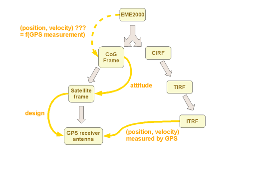
For a given satellite, GPS measurements for position and velocity, expressed in the ITRF2005 frame, are available at any moment.
The GPS antenna is fixed with some offset with respect to the satellite reference frame.
The attitude of the satellite reference frame with respect to some moving frame related to the satellite center of gravity (CoG) is known at any moment.
We want to compute for some instant the position and velocity of the CoG in the EME2000 inertial frame.
A possible solution provided by OREKIT is detailed above.
The CoG frame has its origin at the satellite center of gravity and is aligned with EME2000. It is linked to its parent EME2000 frame by an a priori unknown transform which depends on the current position and velocity. This transform is what we want to compute.
We first build the frame. We use the identity transform as a simple dummy value, the real value which is time-dependent will be recomputed when time is reset:
Frame cogFrame = new Frame(FramesFactory.getEME2000(), Transform.IDENTITY, "LOF");
The satellite frame, with origin also at the CoG, depends on attitude. For the sake of this tutorial, we consider a simple inertial attitude here:
Transform cogToSat = new Transform(new Rotation(0.6, 0.48, 0, 0.64, false));
Frame satFrame = new Frame(cogFrame, cogToSat, "sat");
Finally, the GPS antenna frame is always defined from the satellite frame by 2 transforms: a translation and a rotation. Let's set some values:
Transform translateGPS = new Transform(new Vector3D(0, 0, 1));
Transform rotateGPS    = new Transform(new Rotation(new Vector3D(0, 1, 3),
                                                    Math.toRadians(10)));
Frame gpsFrame         = new Frame(satFrame,
                                   new Transform(translateGPS, rotateGPS),
                                   "GPS");
Let's consider some measurement date in UTC time scale:
TimeScale utc = TimeScalesFactory.getUTC();
AbsoluteDate date = new AbsoluteDate(2008, 10, 01, 12, 00, 00.000, utc);
Then let's get some satellite position and velocity in ITRF2005 as measured by GPS antenna at this moment:
Vector3D position = new Vector3D(-6142438.668, 3492467.560, -25767.25680);
Vector3D velocity = new Vector3D(505.8479685, 942.7809215, 7435.922231);
The transform from GPS frame to ITRF2005 frame at this moment is defined by a translation and a rotation. The translation is directly provided by the GPS measurement above. The rotation is extracted from the existing tree, where we know all rotations are already up to date, even if one translation is still unknown. We combine the extracted rotation and the measured translation by applying the rotation first because the position/velocity vector are given in ITRF frame not in GPS antenna frame:
Transform measuredTranslation = new Transform(position, velocity);
Transform formerTransform =
    gpsFrame.getTransformTo(FramesFactory.getITRF2005(), date);
Transform preservedRotation =
    new Transform(formerTransform.getRotation(),
                  formerTransform.getRotationRate());
Transform gpsToItrf =
    new Transform(preservedRotation, measuredTranslation);
So we can now update the transform from EME2000 to CoG frame.
The updateTransform method automatically locates the frames in the global tree, combines all transforms and updates the single transform between CoG itself and its parent EME2000 frame.
cogFrame.updateTransform(gpsFrame, FramesFactory.getITRF2005(), gpsToItrf, date);
The frame tree is now in sync. We can compute all position and velocity pairs we want:
PVCoordinates origin  = PVCoordinates.ZERO;
Transform cogToItrf   = cogFrame.getTransformTo(FramesFactory.getITRF2005(), date);
PVCoordinates satItrf = cogToItrf.transformPVCoordinates(origin);
Transform cogToEme2000   = cogFrame.getTransformTo(FramesFactory.getEME2000(), date);
PVCoordinates satEME2000 = cogToEme2000.transformPVCoordinates(origin);
As a result, we can compare the GPS measurements to the computed values:
GPS antenna position in ITRF2005: {-6142438.668; 3492467.560; -25767.257}
GPS antenna velocity in ITRF2005: {505.8479685; 942.7809215; 7435.9222310}
Satellite position in ITRF2005: {-6142439.167; 3492468.238; -25766.717}
Satellite velocity in ITRF2005: {505.8480179; 942.7809579; 7435.9222310}
Satellite position in EME2000: {6675100.632; -2317238.909; -31506.077}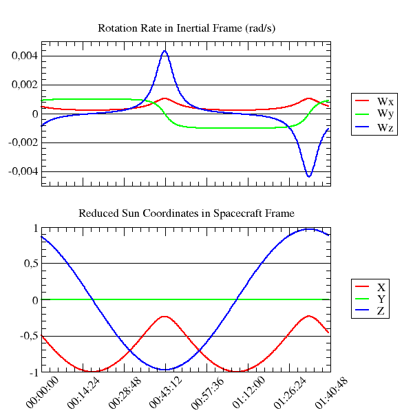
Satellite velocity in EME2000: {-150.5129516; -532.0397437; 7436.0742692}Let's consider a spacecraft which attitude is guided by a yaw steering law, we want to plot some of the effects of such a law on the spacecraft motion.
There was once a SpacecraftFrame in Orekit, but it could not be used in master propagation mode and has been deprecated as of 6.0, so we won't use it. First, an initial orbit for the spacecraft is defined with:
Frame eme2000 = FramesFactory.getEME2000();
AbsoluteDate initialDate = new AbsoluteDate(1970, 04, 07, 0, 0, 00.000,
                                            TimeScalesFactory.getUTC());
double mu =  3.986004415e+14;
Orbit orbit = new CircularOrbit(7178000.0, 0.5e-4, -0.5e-4,
                                Math.toRadians(50.),
                                Math.toRadians(220.),
                                Math.toRadians(5.300),
                                CircularOrbit.MEAN_LONGITUDE_ARGUMENT,
                                eme2000, initialDate, mu);
More details on the orbit representation can be found in the orbits section of the library architecture documentation.
Then the attitude law for the spacecraft is constructed:
double ae =  6378137.0;
double f  =  1.0 / 298.257223563;
Frame itrf2005 = FramesFactory.getITRF2005(true);
BodyShape earth = new OneAxisEllipsoid(ae, f, itrf2005);
NadirPointing nadirLaw = new NadirPointing(earth);
final PVCoordinatesProvider sun = CelestialBodyFactory.getSun();
YawSteering yawSteeringLaw = new YawSteering(nadirLaw, sun, Vector3D.MINUS_I);
More details on the attitude representation can be found in the attitudes section of the library architecture documentation.
As a propagator, we consider an analytic EcksteinHechlerPropagator.
Propagator propagator =
           new EcksteinHechlerPropagator(orbit, yawSteeringLaw, ae, mu,
                                         -1.08263e-3, 2.54e-6, 1.62e-6, 2.3e-7, -5.5e-7);
More details on Propagator can be found in the propagation section of the library architecture documentation.
Then, we associate a step handler with the propagator which directly computes the desired data in spacecraft frame using the current spacecraft state
propagator.setMasterMode(10, new OrekitFixedStepHandler() {

    public void init(SpacecraftState s0, AbsoluteDate t)
        // write file header
    }

    public void handleStep(SpacecraftState currentState, boolean isLast)
        throws PropagationException {

        Transform inertToSpacecraft = currentState.toTransform();
        Vector3D sunInert = sun.getPVCoordinates(currentState.getDate(), currentState.getFrame()).getPosition();
        Vector3D sunSat = inertToSpacecraft.transformPosition(sunInert);
        Vector3D spin = inertToSpacecraft.getRotationRate();

        // write data to file

    }

}
So, computing over an orbit, we can plot the following results showing clearly a typical yaw steering behavior: