The top level design describes the various libraries and their interactions. The lowest level corresponding to the Hipparchus library is not shown here for clarity.
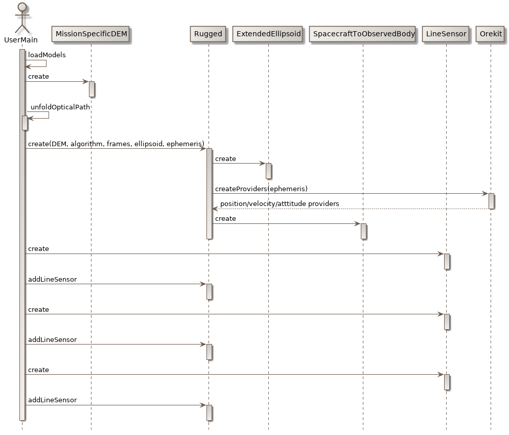
The following sequence and class diagrams show the three most important functions: initialization of the libraries, direct location and inverse location.
The user of the Rugged library is responsible to provide its main program and a mission specific Digital Elevation Model loader, in the form of a class implementing Rugged TileUpdater interface. He also creates a LineSensor containing the geometry of the pixels line-of-sights. He then creates an instance of the top-level Rugged class and provides it the created objects as well as its selection of options for algorithm, ellipsoid and frame choices.
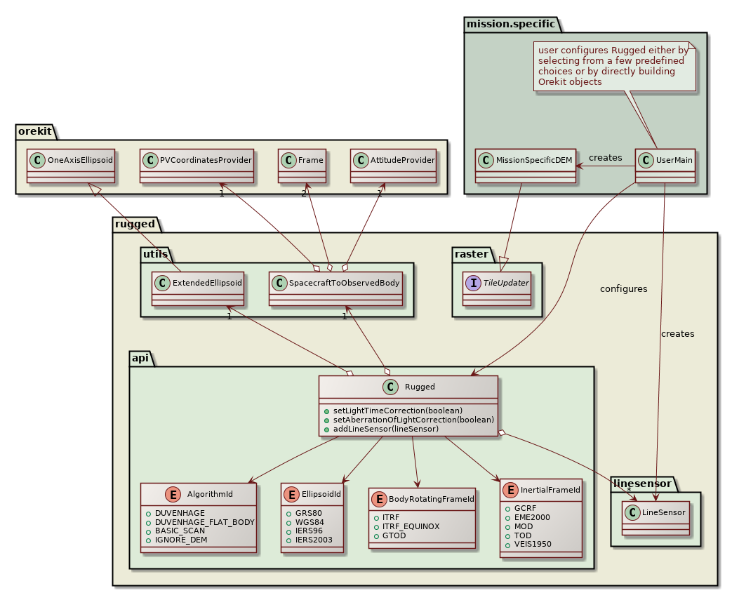
The Rugged instance will store everything and create the various objects defining the configuration (creating the algorithm, ellipsoid and frames from the identifiers provided by the user. Using simple enumerates for frames or ellipsoid allow a simpler interface for regular users who are not space flight dynamics experts. For expert use, the user can also create these objects directly and pass them to Rugged if the predefined identifiers do not cover his needs. As shown in the following figure, several line sensors can be added to a single Rugged instance, this is intended to compute correlation grid, when images coming from two different sensors are expected to be accurately combined.
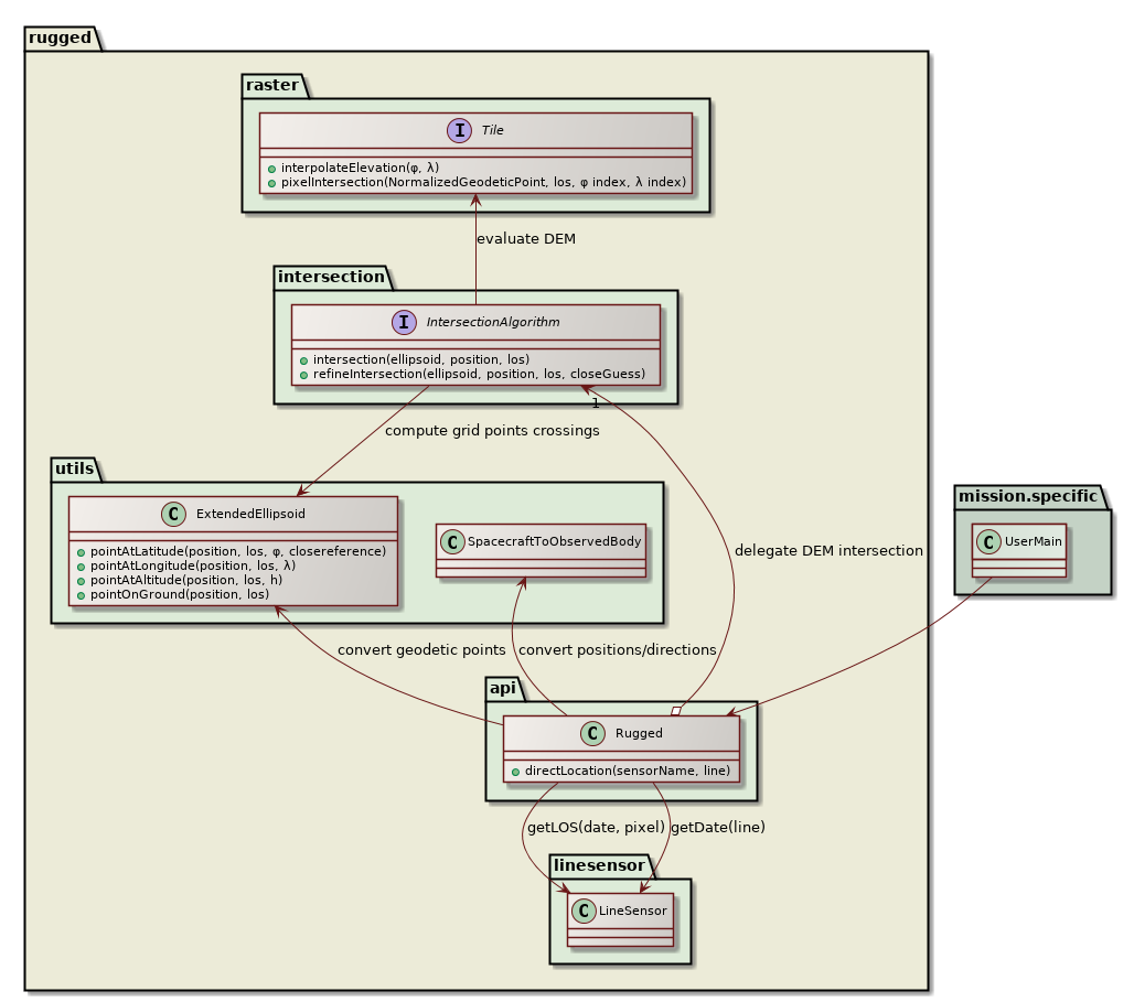
Direct location is called a large number of times by the application, once for each sensor line. The application only provides image processing related data to the configured Rugged instance, i.e. the line number, and it expects the geodetic coordinates of the ground points corresponding to each pixels in the sensor line. The Rugged instance will delegate conversions between frames to an internal SpacecraftToObservedBody converter, the conversions between Cartesian coordinates and geodetic coordinates to an internal ExtendedEllipsoid object, and the computation of the intersection with the Digital Elevation Model to the algorithm that was selected by user at configuration time.
The pixels independent computation (orbit and attitude interpolation, Earth frame to inertial frame transforms, transforms composition) are performed only once per date inside the caching combined transform provider set up at initialization time and the resulting transform is applied for all pixels in the line, thus saving lot of computing power.
The innermost loop is the correction of each pixel, which is split in the line-of-sight to ellipsoid intersection, and followed by the Digital Elevation Model intersection. The callback to the mission specific interface to retrieve DEM raw data is called from the inner loop but is expected to be triggered only infrequently thanks to a caching feature done at Rugged library level.
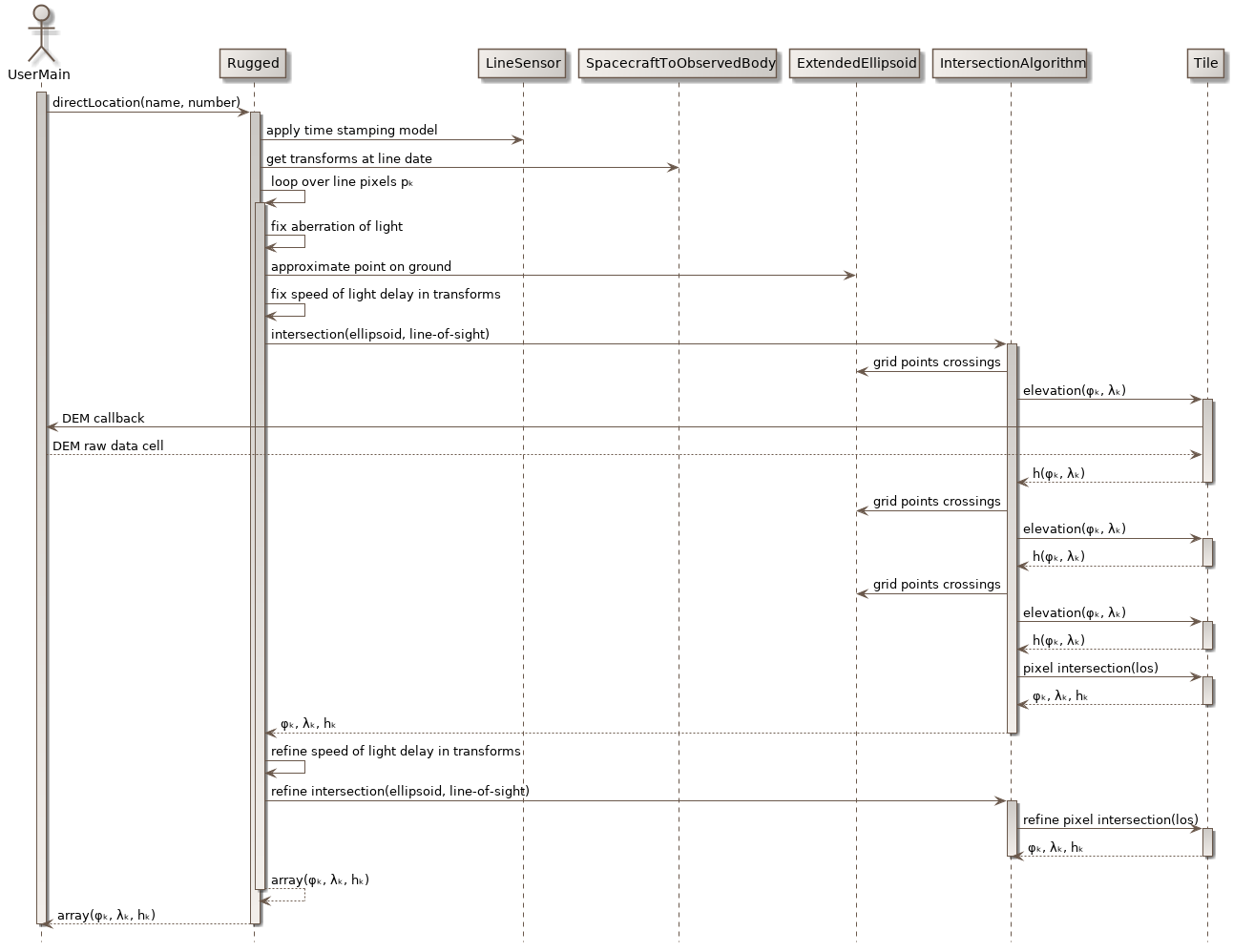
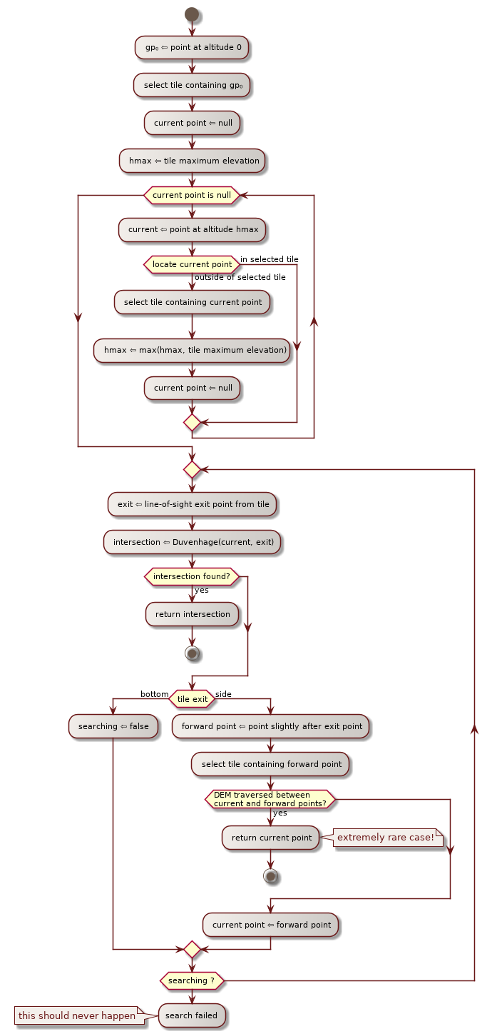
The following figure describes the algorithm used for tile selection and how the underlying intersection algorithm (Duvenhage in this example) is called for one tile:
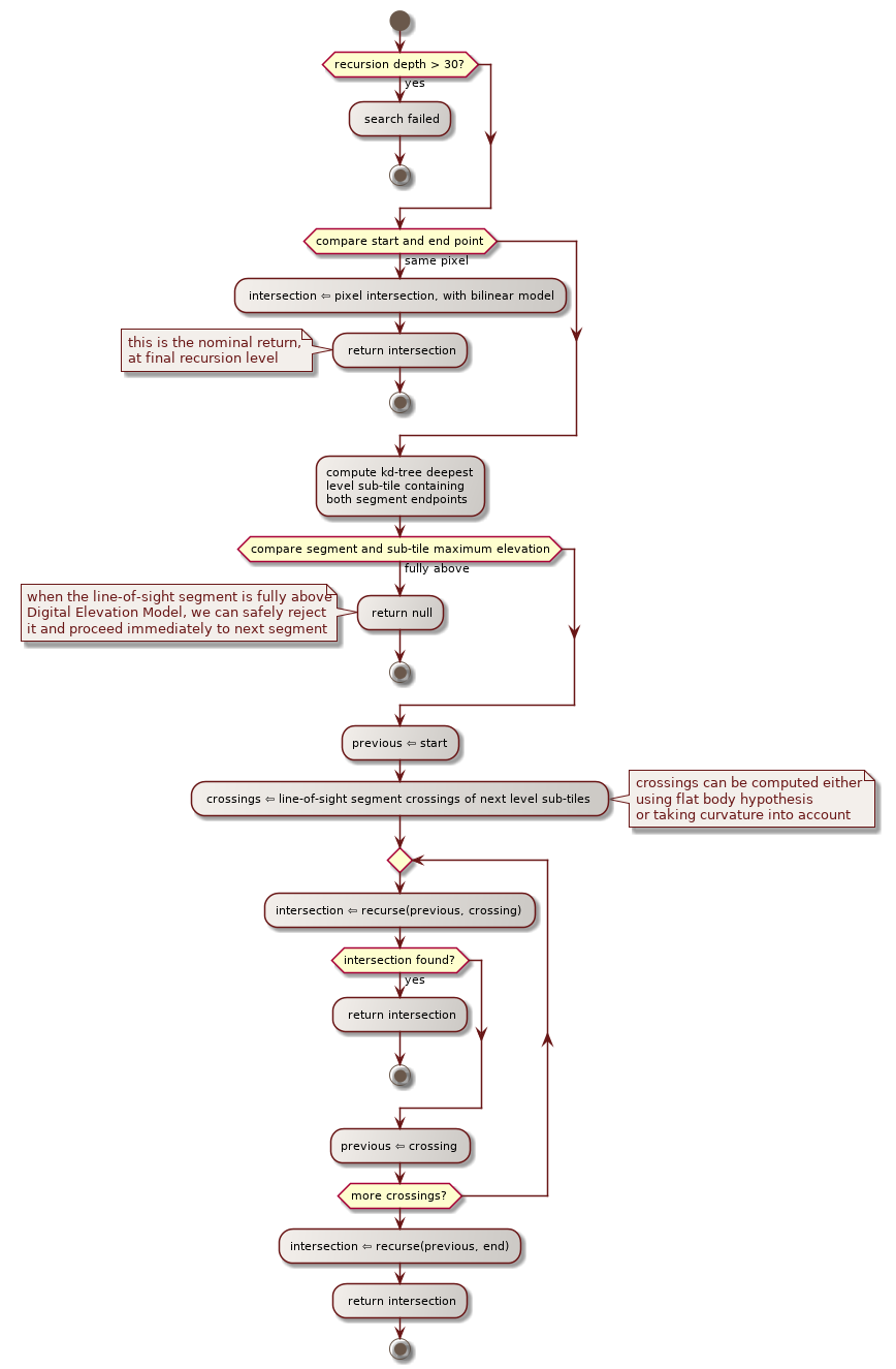
The recommended Digital Elevation Model intersection algorithm is the Duvenhage algorithm. The following figure describes how it is implemented in the Rugged library.
Inverse location is called a large number of times by the application, typically on a regular grid in some geographic reference like UTM. The application only provides image processing related data, i.e. the geodetic coordinates of the ground points and expects the coordinates of the corresponding pixel (both line number of pixel number). The pixels independent computation (orbit and attitude interpolation, Earth frame to inertial frame transforms, transforms composition) are performed only once per line and cached across successive calls to inverse location, thus greatly improving performances.
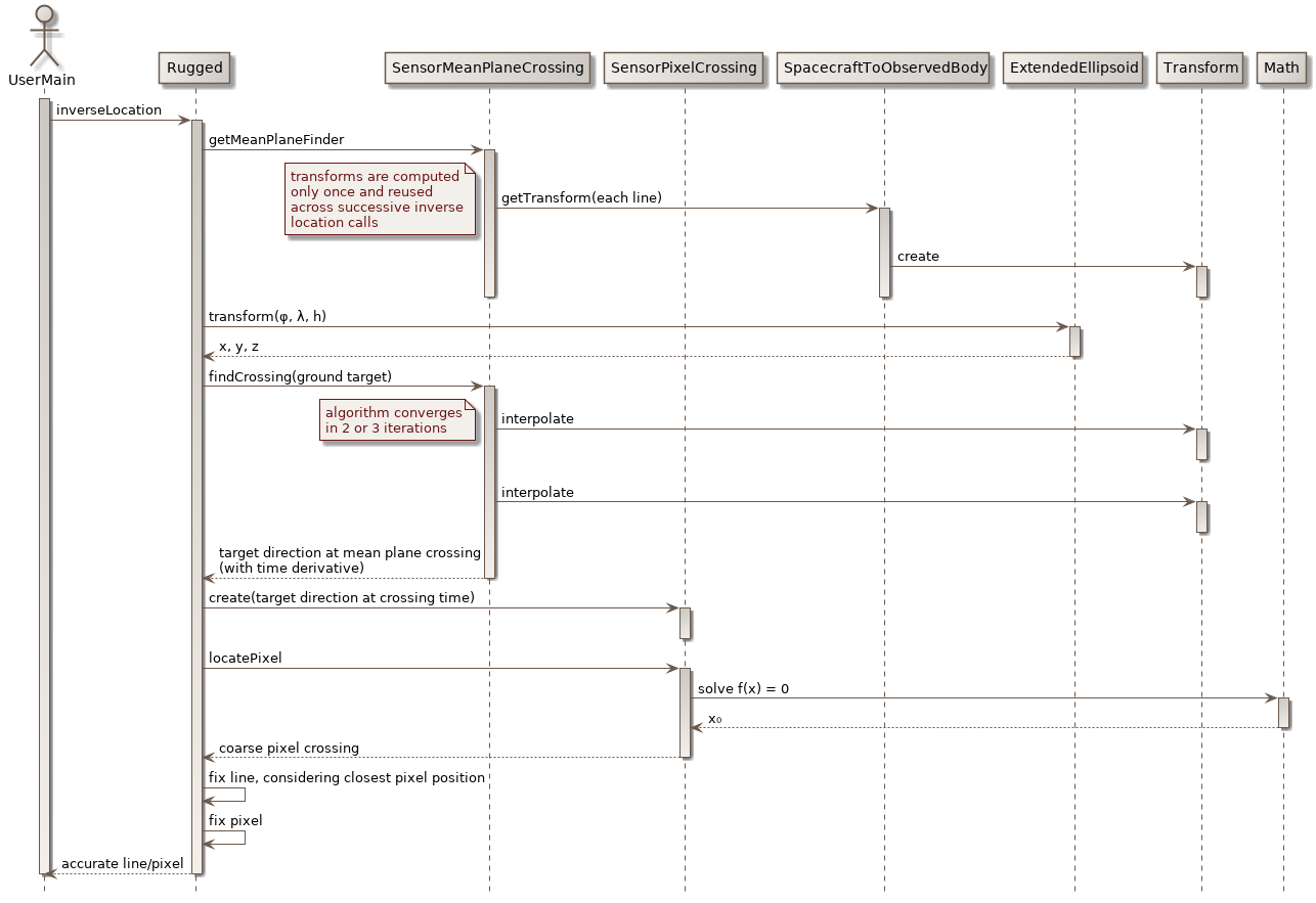
The computation is performed in several steps. The line to which the points belong is first searched using a dedicated solver taking advantage of the first time derivatives automatically included in Orekit transforms. It can therefore set up a model of the angle between the target point and the mean sensor plane, and therefore compute in only two or three iterations the exact crossing of this plane, and hence the corresponding line number. Then, the position of this crossing along the line is searched using a general purpose solver available in Hipparchus. As all coordinates are already known in spacecraft frame at this stage, no conversions are performed and this solver find the corresponding pixel very fast. The last two steps correspond to fixing accurately the previous results, which can be important when the various pixels in the line sensor do not really form an exact line and therefore when the previous computation which were done using a mean plane do not represent reality. These final fixes are simple to do because instead of providing simple values as results, the first step in fact provided a Taylor expansion, thus allowing to slightly shift the result at will.
The Digital Elevation Model is used at a very low level in the Rugged library, but read at a high level in the mission specific interface library. The following design has been selected in order to allow the lower layer to delegate the implementation of the loading to the upper layer, and to avoid too many calls. The driving principle is to set up a cache for DEM tiles, keeping a set of recently used tiles in memory up to a customizable maximum number of tiles, and asking for new tiles when what is in memory does not cover the region of interest.
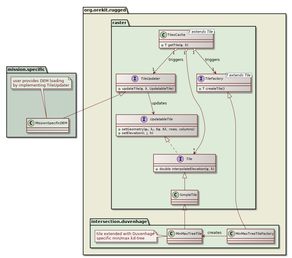
The cache and the tiles themselves are implemented at Rugged library level. The loader is implemented at mission specific interface level, by implementing the TileUpdater interface, which defines a single updateTile method. When this updateTile method is called by the cache, one of its argument is an UpdatableTile instance that must be updated. The implementation must first call once the setGeometry method to set up the global geometry of the tile (reference latitude and longitude, latitude step size, longitude step size, number of rows and columns in the raster), and then call the setElevation method for each element of the raster. The loader can therefore avoid to allocate by itself a large array that will in any case be reallocated by the Tile. The loader only sees interfaces in the API and doesn’t know anything about the real specialized tiles that are used under the hood. Different DEM intersection algorithms can use different tiles implementations without any change to the mission specific interface. One example of this independence corresponds to the Duvenhage algorithm, has in addition to the raw elevation grid, the tile will also contain a min/max kd-tree, so there are both a dedicated specialized tile and a corresponding TileFactory in use when this algorithm is run.