As Rugged is built on top of Orekit and Hipparchus, all the flight dynamics and mathematical computation are delegated to these two libraries and the full accuracy available is used. This implies for example that when computing frames conversions between the inertial frame and the Earth frame, the complete set of IERS Earth Orientation Parameters (EOP) corrections is applied if the IERS files are available. This may lead to results slightly different from the one produced by some other geometry correction libraries that are limited to the older equinox-based paradigm (Mean Of Date and True Of Date), apply only DUT1 and pole wander corrections and ignore the other Earth Orientation Parameters corrections. The expected difference with such libraries is due to the missing corrections (δΔε and δΔψ for equinox-based paradigm) to the IAU-1980 precession (Lieske) and nutation (Wahr) models used in the legacy MOD and TOD frames.
The following figure is a plot of this error, showing the coordinates of three Earth points along the three canonical X, Y and Z axes, roughly at Earth radius. The plot shows a clear regular signal with several harmonics, which correspond to the nutation components that were not in this older model. This error was small in the 80’s but is much higher now (as of 2014, it is of the order of magnitude of 3 meters). The error is steadily increasing.
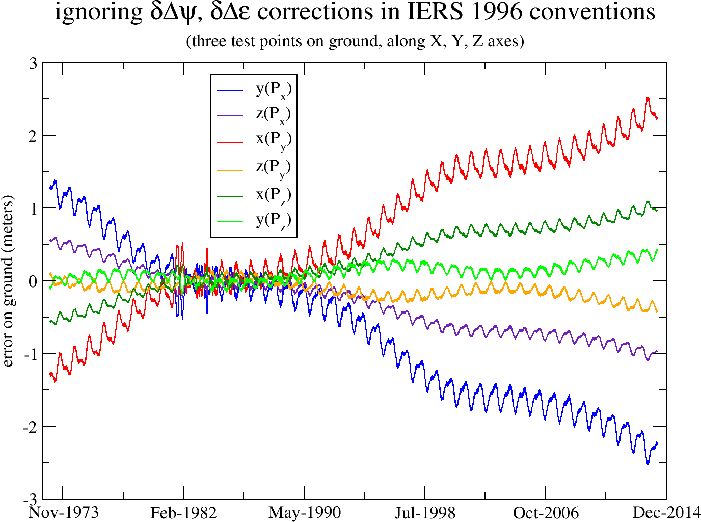
Note that this error occurs when the initial data for spacecraft position is initially given in inertial frame and must be converted to Earth frame. This typically occurs in mission analysis phases as the spacecraft position is computed from orbit propagation. It is however not always the case in operational systems where the position is not provided by orbit propagation but rather by on-board GPS system which already work in Earth frame and do know about the full corrections. In these operational cases, the error is less important as it applies only to the conversion of the attitude quaternions (which are typically given in inertial frame as they are often produced by star trackers).
As Rugged delegates computation to Orekit, the full set of corrections (DUT1, pole wander, lod, δΔε/δΔψ or δx/δy) are automatically loaded and applied. The final accuracy obtained when all EOP are considered is at sub-millimeter level in position, and the expected difference with libraries ignoring δΔε and δΔψ is at a few meters level, Rugged being the more accurate one.
These legacy models are very old and not recommended anymore by IERS since 2003. IERS also currently still provides the correction for these models, but there is no guarantee they will do so indefinitely, as they are now providing corrections with respect to newer and more accurate models. The newer frames are based on a non-rotating origin paradigm and on different precession and nutation models (IAU-2000/2006), which are much more accurate. The corresponding corrections (δx/δy, not to be confused with the xp/yp pole wander) are smaller because the precession and nutation models are better than the former ones. The much better accuracy of these new models can be seen doing the same kind of plot as before, i.e. ignoring temporarily the IERS corrections. The following figure shows the result.
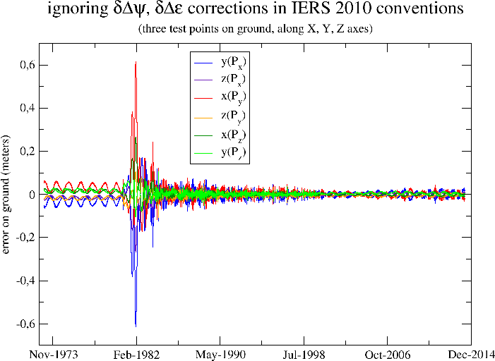
The remaining error is very small, of the order of magnitude of 2 or 3 centimeters. Rugged is not limited to the legacy MOD and TOD frames and can use the newer IERS recommended frames as well. From a user perspective, this is completely unnoticeable as user simply selects an Earth frame as an existing predefined object by name, and doesn’t have to care about the transforms and corrections. In fact at Rugged level there is not even a notion of precession, nutation or EOP corrections. The only interfaces used are the inertial and Earth frames names and the date. From these three elements, Orekit computes all geometrical transform, including both the theoretical motion models and the IERS corrections, thus greatly leveraging the computation.
One consequence of using newer precession and nutation models is that as shown in previous figure, even when the EOP corrections are not available yet (typically for near real-time analysis of images), it is still possible to compute very accurately the geometry of the image.
As a summary, Rugged may give results slightly more accurate than other geometric correction libraries, and is compatible with both the legacy frames and the newer frames.
The global geometry of the image depends on the spacecraft position and attitude. Both are obtained using any Orekit provided propagators. Thanks to the architecture of the Orekit propagation framework, propagation can be either a true propagation from an initial state (which is interesting in mission analysis and simulation use cases) or can be an interpolation from a loaded ephemeris. From the caller point of view, there are no differences between the two cases, as an ephemeris is a special case of propagator, using interpolation from its loaded sample. Support for CCSDS-based ephemerides is already provided by Orekit, and it is possible to build ephemerides from lists of states if a dedicated loader is developed to parse mission-specific files.
When ephemeris interpolation is selected as the underlying propagator, the number of points used for the interpolation is specified by the user, so simple linear model is possible but higher degree interpolation is available. The interpolation retains the raw state format, so if an ephemeris contains circular orbital parameters, interpolation will be done using these parameters whereas if ephemeris contains position and velocity, interpolation will be done using position and velocity. As velocity is the time derivative of position, in this case a Hermite interpolation is performed, thus preserving derivatives consistency.
Dedicated algorithms are implemented in Orekit to deal with quaternions interpolation. Direct polynomial interpolation of the four quaternion components does not work reliably, and even less if only linear interpolation is performed, even if normalization is used afterwards. The first reason for this bad behaviour is very crude accuracy of linear only models. The second reason is that despite quaternion Q1 and -Q1 represent the same rotation, interpolating components between Q1 and Q2 or -Q1 and Q2 leads to completely different rotations, and the quaternions in an ephemeris will typically have one sign change per orbit at some random point. The third reason is that instead of doing an interpolation that respect quaternions constraint, the interpolation departs from the constraint first and attempts to recover afterwards in a normalization step. Orekit uses a method based on Sergeï Tanygin’s paper Attitude interpolation with slight changes to use modified Rodrigues vectors as defined in Malcolm D Shuster’s A Survey of Attitude Representations, despite attitude is still represented by quaternions in Orekit (Rodrigues vectors are used only for interpolation). These changes avoid a singularity at π. Some other refinements have been added to also avoid another singularity at 2π, but these refinements are mostly useful for either spin-stabilized spacecrafts with high rotation rate or for interpolation over large time spans when the attitude spans over more than a full turn, so they will probably not be triggered in the context of Earth observation spacecrafts.
The different interpolation scheme is however expected to lead to only very small differences in numerical accuracy in the traditional cases with respect to simple linear interpolation on quaternion components followed by normalization. The reason for this unexpected good behaviour is because in traditional image processing applications, the step size used for the quaternion are often very small. The bad behavior of linear interpolation of quaternion components appears only for step sizes above one minute, which are seldom used in image processing.
As a summary, Rugged relies on either propagation or interpolation at user choice, and attitude interpolation is much more sophisticated than linear interpolation of quaternion components, but no differences are expect at this level, except for simpler development and validation as everything is readily implemented and validated in Orekit.
At spacecraft level, the optical path is folded due to the various reflections and positions of the sensors with respect to the spacecraft center of mass. Following this assumption, the path can be virtually unfolded using the laws of optical geometry and replaced by a straight line in spacecraft vicinity, with virtual pixels locations and lines of sights defined by simple vectors with respect to the center of mass. As both position and orientation are considered, this implies that the pixels are not considered exactly co-located with the spacecraft center of mass, the offset is typically of meter order of magnitude. If for example we consider a 3m long spacecraft with an instrument is on the front (+X), the offset would be about 1.5m if center of mass were at spacecraft mid-length.
This path unfolding is done once at geometry loading by the interface layer above the Rugged library, using the services provided by Rugged line-of-sight builder, so all further computation are done with simple straight lines. Of course, if the spacecraft definition file does not include position informations, only the various reflections are taken into account and the location of the sensor is co-located with spacecraft center of mass.
The various transformed applied when building the lines-of-sight may be time-dependent to take into account slow variations like thermo-elastic effects. Their parameters can also be estimated in calibration phases.
As pixel/ground mapping is computed, all intermediate geometric computation (attitude, orbit, precession, nutation, EOP corrections, Earth rotation, pole wander) are combined into a couple of accurate Transform instances. These transforms are then applied a few thousand times to convert every pixels line-of-sight in Earth frame. The reason for this computation scheduling is that the transform between inertial frame and Earth frame is computing intensive and only depends on date, so factoring it out of the pixels loop is a huge speed-up. As Orekit provides a way to combine several Transform instances together first and apply them to positions and directions later, a lot of computation steps can be saved by also including all conversions up to spacecraft frame.
As observation satellites are about 800km above ground, the light coming from the ground points they look at left Earth about 2.7ms before arriving on the sensors. This implies that the exact position of the ground point must be computed at an earlier time than the position of the spacecraft. The expected difference can be predicted as the rotation of Earth during the 2.7ms light travel time, it is about 1.2m at equator, in the East-West direction. This effect is compensated by applying the so-called light-time correction.
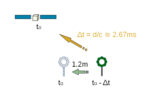
The delay is computed for each pixel as the travel time is shorter for pixels looking in the nadir direction than for pixels looking at the edge of field of view. As Orekit frame transforms automatically include a local Taylor expansion of the transform, compensating the differential Earth rotation during this 2.7ms delay is done without recomputing the full precession/nutation model, so the computation savings explained in the paragraphs above are still available when this compensation is applied.
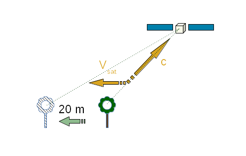
Aberration of light is another phenomenon that must be considered. Aberration of light is the apparent shift in direction of an incoming light when seen from a sensor that is itself moving. This shift is independent of the motion of the source of the light, it depends only on the current velocity of the sensor at time of arrival. It is a composition of two velocities, the velocity of light and the velocity of sensor. This composition can be computed simply in classical mechanics or with a slightly more complex equation with relativistic effects. As spacecraft velocities are limited, classical mechanics is sufficient for accurate correction. This effect is a large one and can correspond to up to a 20m shift once projected on ground for classical Earth observing missions.
As shown in next figure, from spacecraft point of view, the light incoming from the ground point seems to come from a fictitious point “ahead” of the real point.
As a side note, aberration of light and light time correction can be linked or considered to be two aspects of a similar phenomenon, even in classical (non-relativistic) physics. It depends on the frame in which we look at the various elements. If the source is moving and the observer is at rest (i.e. we do the computation in the observer frame), then there is only light time correction and aberration of light is zero. If the source is at rest and the observer is moving (i.e. we do the computation in source frame), then there is only aberration of light (this is how aberration of light was first experimentally identified, in the context of astronomy, considering the motion of Earth from where astronomers observe stars) and light time correction is zero. In the Rugged context, both source and observer move with respect to the inertial frame into which we do the correction computation: the source moves due to Earth rotation, the observer moves due to spacecraft orbit. So in Rugged context, both phenomenoms exist and should be compensated. Some other systems may consider only one of the two phenomena and produce accurate results, simply by computing the correction in either Earth or spacecraft frame and considering the motion of the other part as a relative motion combining both Earth and spacecraft: it is really only a matter of point of view.
Both light-time correction and aberration of light correction are applied in the Rugged library for greater accuracy, but both can be ignored (independently) at user choice. One use case for ignoring these important correction is for validation purposes and comparison with other libraries that do not take this correction into account. This use case is by definition restricted to validation phases and should not apply to operational systems. Another use case for ignoring light-time correction and aberration of light correction occurs when the effect is explicitly expected to be compensated at a later stage in the image processing chain, most probably using a posteriori polynomial models. This use case can occur in operational products. It seems however better to compensate these effects early as they can be computed to full accuracy with a negligible computation overhead.
Once a pixel line-of-sight is known in Earth frame, computing its intersection with a reference ellipsoid is straightforward using an instance of OneAxisEllipsoid. The Orekit library computes this intersection as a NormalizedGeodeticPoint instance on the ellipsoid surface.
The line-of-sight is a straight line in the Cartesian 3D space, and once converted to geodetic coordinates (latitude, longitude, altitude), it is not a straight line anymore. Assuming line-of-sight remains a straight line in this space and can be defined by computing only two points10 introduces yet another error, which is transverse to line-of-sight and reaches its maximum value roughly at middle point. This assumption is a flat-body assumption, i.e. it correspond to locally approximating the ellipsoid to its tangential plane. The error is the sagitta due to the bending of the real line-of-sight in the geodetic space.
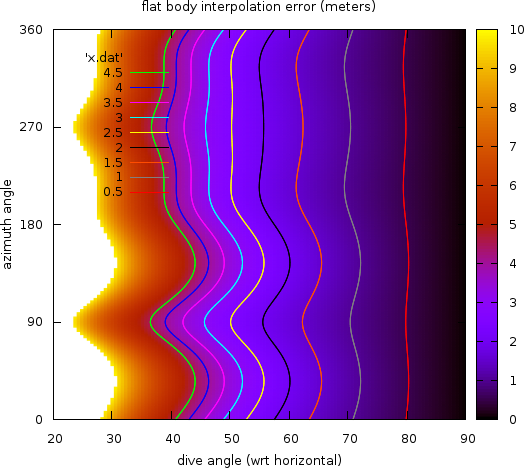
This error depends on the diving angle of the line-of-sight with respect to local vertical. It is zero for a diving angle of 90 degrees (i.e. a pure nadir line-of-sight) and increases as the diving angle decreases. It can reach tremendous values (hundreds of meters or more) for almost tangential observations. The previous figure shows the amplitude of the error as a function of both the diving angle and the azimuth of the observation. It was computed for a ground point at intermediate latitude (about 54 degrees North, in Poland), and using the two base points for the line-of-sight segment at 8000 meters altitude and -400 meters altitude.
The Rugged library fully computes the shape of the line-of-sight throughout its traversal of the Digital Elevation Model when the Duvenhage algorithm (see next section) is used for DEM intersection. For testing purposes, another version of the algorithm assuming flat-body hypothesis is also available (i.e. it consider the line-of-sight is a straight line in latitude/longitude/altitude coordinates) but its use is not recommended. The computing overhead due to properly using ellipsoid shape is of the order of magnitude of 3%, so ignoring this on the sake of performances is irrelevant.
The following table summarizes the error compensations performed in the Rugged library which are not present in some other geometry correction libraries:
| origin | amplitude | location | comment |
|---|---|---|---|
| δΔε and δΔψ corrections for precession and nutation models | > 3m | horizontal shift | up-to-date precession and nutation models are also available, the error is much smaller if positions are already in Earth frame and only attitude is converted |
| quaternion interpolation | negligible | line-of-sight direction | the effect is important for step sizes above 1 minute |
| instrument position | 1.5m | along track | coupled with attitude |
| light time correction | 1.2m | East-West | pixel-dependent, can be switched off if compensated elsewhere in the processing chain |
| aberration of light | 20m | along track | depends on spacecraft velocity, can be switched off if compensated elsewhere in the processing chain |
| flat-body | 0.8m | across line-of-sight | error increases a lot for large fields of view, can be switched off, but this is not recommended |